Posts

RADAR AND ITS APPLICATION

Image
RADAR  was coined in 1940 by the United States Navy as an acronym for Radio Detection and Ranging or Radio Direction and Ranging. Radar is an object-detection system that uses radio waves to determine the range, angle, or velocity of objects. It can be used to detect aircraft, ships, spacecraft, guided missiles, motor vehicles, weather formation and terrain. Radar was developed secretly for military use by several nations in the period before and during World War II (1 September 1939 – 2 September 1945). Click here for accessing complete document.

Design of Helical Antenna using HFSS Software.

Image
EXPERIMENT NO: 04 Aim: Design of Helical Antenna using HFSS Software. SOFTWARE USED: ANSYS HFSS 15.0.3 THEORY: For the design of helical antenna, software tool HFSS is used for modeling the structure. HFSS stands for High Frequency Structure Simulator and is propriety software of Ansoft Corporation. Based on the available equations, design parameter of the helical antenna is calculated. Click here for complete manual of this experiment.

Design of Yagi Uda Antenna Using HFSS Software.

Image
EXPERIMENT NO: 03 AIM: Design of Yagi Uda Antenna Using HFSS Software. SOFTWARE USED: ANSYS HFSS 15.0.3 THEORY: A Yagi–Uda antenna, commonly known as a Yagi antenna, is a  directional antenna  consisting of multiple parallel elements in a line, usually  half-wave dipoles  made of metal rods. Yagi–Uda antennas consist of a single  driven element  connected to the  transmitter  or  receiver  with a  transmission line , and additional " parasitic elements " which are not connected to the transmitter or receiver: a so-called reflector and one or more directors.  It was invented in 1926 by  Shintaro Uda  of  Tohoku Imperial University ,  Japan , and (with a lesser role played by his colleague)  Hidetsugu Yagi . The reflector element is slightly longer than the driven dipole, whereas the directors are a little shorter. This design achieves a very substantia...

Simulation of Microstrip Patch Antenna using HFSS software with analysis of rectangular plot, polar plot and smith chart.

Image
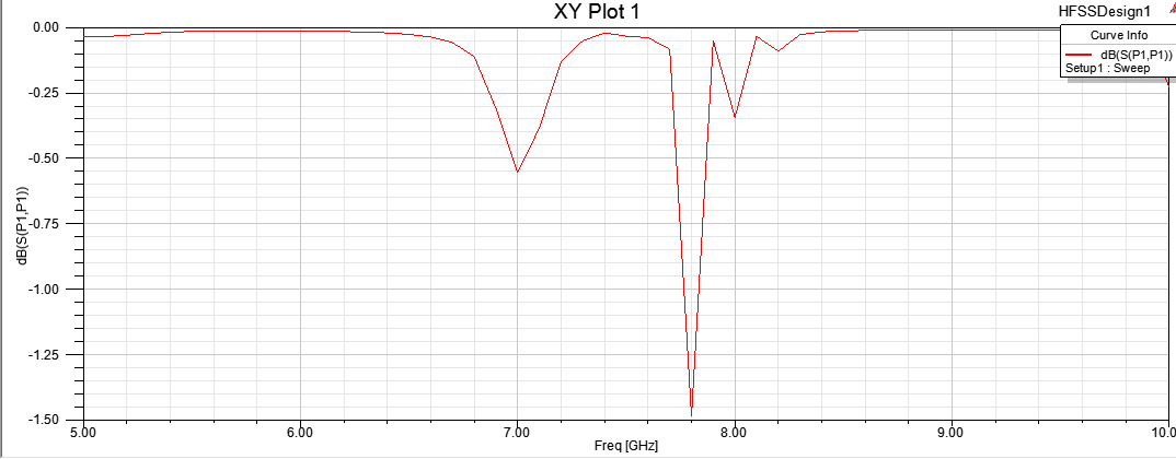
Microwave Engineering Lab (BTEC-606) Experiment No: 2 AIM: Simulation of Microstrip Patch Antenna using HFSS software with analysis of rectangular plot, polar plot and smith chart. SOFTWARE USED: ANSYS HFSS 15.0.3 THEORY: Microstrip Patch Antenna:  A patch antenna (also known as a rectangular microstrip antenna) is a type of radio antenna with a low profile ( small height and width ), which can be mounted on a flat surface. It consists of a flat rectangular sheet or "patch" of metal, mounted over a larger sheet of metal called a ground plane. In  telecommunication , a microstrip antenna (also known as a printed antenna) usually means an  antenna  fabricated using  microstrip techniques on a  printed circuit board  (PCB). They are mostly used at  microwave   frequencies . An individual microstrip antenna consists of a patch of metal foil of various shapes (a  patch antenna ) on...

Introduction to ANSYS HFSS software and Design Methodology of Microstrip Patch Antenna.

Image
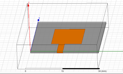
Microwave Engineering Lab (BTEC-606) Experiment No: 1 AIM: Introduction to ANSYS HFSS software and Design Methodology of Microstrip Patch Antenna. SOFTWARE USED: ANSYS HFSS 15.0.3 THEORY: HFSS (High Frequency Structure Simulator) software: It is one of several commercial tools used for  antenna  design, and the design of complex  RF   electronic circuit  elements including filters, transmission lines, and packaging. It was originally developed by Professor Zoltan Cendes and his students at Carnegie Mellon University. ANSYS was founded in 1970. By John A. Swanson as “Swanson Analysis Systems, Inc.” (SASI). In 1994, new owners took SASI's leading software, called ANSYS, as their flagship product and designated ANSYS, Inc. as the new company name. There is no proved explanation but we can say that ANSYS represents “Analysis System”.   Microstrip Patch Antenna:  A patch antenna (also known as a rectangular microstrip ante...