Design of Yagi Uda Antenna Using HFSS Software.
EXPERIMENT
NO: 03
AIM:
Design of Yagi Uda Antenna Using HFSS Software.
SOFTWARE
USED: ANSYS HFSS 15.0.3
THEORY:
A Yagi–Uda antenna, commonly known as a Yagi antenna, is a directional antenna consisting of multiple
parallel elements in a line, usually half-wave
dipoles made of metal rods. Yagi–Uda antennas consist of a
single driven element connected to the transmitter or receiver with
a transmission line, and additional "parasitic
elements" which are not connected to the transmitter or
receiver: a so-called reflector and
one or more directors.
It was invented in 1926 by Shintaro Uda of Tohoku
Imperial University, Japan, and (with a lesser
role played by his colleague) Hidetsugu
Yagi. The reflector element is slightly longer than the driven
dipole, whereas the directors are a little shorter. This design achieves a
very substantial increase in the antenna's directionality and gain compared
to a simple dipole.
Also called a "beam antenna", or
"parasitic array", the Yagi is very widely used as a high-gain
antenna on the HF, VHF and UHFbands.
(source: Wikipedia)
(source: Wikipedia)
PROCEDURE:
1.
Open the HFSS software window.
2.
Go to
file and create new.
3.
Press
“Insert HFSS design” option in upper left side of window.
4.
Draw
cylinder of random dimension in y-axis and set the following parameters.

1.
Go to
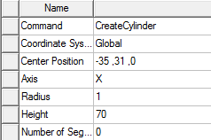
create cylinder under antenna and set the following parameters.


It looks like this:

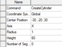
1. Similarly
create another cylinder for antenna 1 with following parameters value.

1. Create
cylinder of antenna 1 specification:

1. Create
cylinder of antenna 2 specification:
1. Create
cylinder of antenna 3 specification:

1. Create
cylinder of antenna 4 specification:

1. Create
cylinder of antenna 5 specification:

1. Create
cylinder of antenna 6 specification:

1. Create
cylinder of antenna 7 specification:

1. Create
cylinder of antenna 8 specification:

Create cylinder of antenna 9 specification:

1. Create
cylinder of antenna 10 specification:
1. Create
cylinder of antenna 11 specification:

1. Create
cylinder of antenna 12 specification:

1. Create
cone with following specification:


1. Create
small circle with following specification.

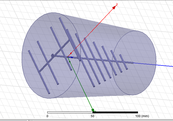
Finally the design looks like this:


Comments
Post a Comment