Introduction to ANSYS HFSS software and Design Methodology of Microstrip Patch Antenna.
Microwave
Engineering Lab (BTEC-606)
Experiment
No: 1
AIM:
Introduction to ANSYS HFSS software and Design Methodology of Microstrip Patch
Antenna.
SOFTWARE
USED: ANSYS HFSS 15.0.3
THEORY:
HFSS
(High Frequency Structure Simulator)
software: It is one of several
commercial tools used for antenna design, and the design of complex RF electronic circuit elements
including filters, transmission lines, and packaging. It was originally
developed by Professor Zoltan Cendes and his students at Carnegie Mellon University.
ANSYS was founded in 1970. By John A. Swanson as “Swanson
Analysis Systems, Inc.” (SASI). In 1994, new owners took SASI's leading
software, called ANSYS, as their flagship product and designated ANSYS, Inc. as
the new company name. There is no proved explanation but we can say that ANSYS
represents “Analysis System”.
Microstrip Patch Antenna: A patch antenna (also known as a rectangular
microstrip antenna) is a
type of radio antenna with
a low profile (small
height and width), which
can be mounted on a flat surface. It consists of a flat rectangular sheet or
"patch" of metal,
mounted over a larger sheet of metal called a ground plane.
In telecommunication, a microstrip antenna (also
known as a printed antenna)
usually means an antenna fabricated
using microstrip techniques on a printed
circuit board (PCB). They are mostly used
at microwave frequencies. An individual microstrip antenna consists of a patch of
metal foil of various shapes (a patch antenna) on the surface of a PCB, with a metal foil ground
plane on the other side of the board. Most
microstrip antennas consist of multiple patches in a two-dimensional array. The
antenna is usually connected to the transmitter or receiver through
foil microstrip transmission
lines. Microstrip antennas have become very popular
in recent decades due to their thin planar profile which can be incorporated
into the surfaces of consumer products, aircraft and missiles, their ease of
fabrication using circuit techniques, the ease of integrating the antenna on the same board with
the rest of the circuit, and the possibility of adding active devices such
as microwave integrated circuits to the antenna itself to make active
antennas.
PROCEDURE:
1.
Open the
HFSS software window.
2.
Go to
file and create new.
3.
Press
“Insert HFSS design” option in upper left side of window.
4.
Draw Box
randomly along the x-y-z axis.
5.
Fill the
Box properties as per the given window and press Ok.
6.
double
click on “CreateBox” under substrate and place the value as per the below
screen:
7.
Again create Box and set the properties as
per the following instruction:
8.
Go to
CreateBox and set the properties as per the figure below:
9.
Create a
box for feedline and set the properties as per the given below:
Name: feed_line
Position: 10.9375,0,0
Material: “pec”
Xsize: 2.46
Ysize 8
Z=0.05
Color: orange
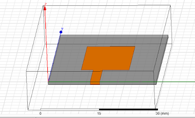
10. Create a box for patch which is connected with
feedline
Name: patch
Position: 7.825,8,0
Xsize: 12.45
Ysize: 16
Zsize: 0.05
Color: Orange
11. Press Ctrl and select patch and feedline and
select unite button.
12. Go to patch-assign Boundary-perfect E as per
the below pic:
Name: PerfE_patch
Similarly: ground_plane-boundary
condition-perfect E
Name: PerfE_ground
13. Use airbox for radiation
14. Copy substrate and paste it
15. Press Esc
to stop rotate and zoom
16. Press E to select edges-go to
modeler-edge-create object from edge
17. Go to draw-sweep-along vector
18. Just give it random value and hit OK
19. Now some material have been come out from the
feedline
20. Go to patch object from edge 1 and fill
accordingly:
21. Press sweep along vector
22. Vector: o,o,-h 31 mil
23. The adding material has been vertical attached
with feedline
24.


Nice Blog. Thanks for Sharing and Keep Posting. Antenna Design and Simulations in India
ReplyDelete